- Posts: 3199
- Thank you received: 928
Setting angles of engine/drivelines in chassis
6 years 5 months ago #188810
by Dave_64
Setting angles of engine/drivelines in chassis was created by Dave_64
Is there any hard and fast rule as to what angle the engine/transmission should sit in relation to the truck chassis?
Bear with me a minute here and I'll try and explain what I'm after.
The bare chassis (unsprung) is sitting on the garage floor, got some adjustable stands here so by running a spirit level or straight edge along the top of the chassis rail, reckon I can get it pretty near spot on lengthwise and crossways.
At the moment, the front of the engine is jacked up with blocks and spacers to get it within the ball park, if I check the angle with a straight edge across the face of the harmonic balancer, get a reading on the iphone angle meter of 5.7*, checking the output flange on the transmission also gives the same reading, 5.7*. So far so good. When I check across the face of the diff flange, gives a reading on the same meter of 8.2*.
Obviously (going by the Spicer uni-joint bible) this is a bit too much for the length of the tailshaft I will end up with. Not too worried about the diff at this stage, as I can always put wedges between the springs/saddles if I end up a bit out.
What I'm trying to work out, is if you draw an imaginary line through the centre of the crankshaft (i.e. from the harmonic balancer through to the output flange on the transmission) at what angle should it be to the line of the actual chassis?
Is there any rule here? Or does it really matter if the angles are nearly flat?
I have the rear crossmembers bolted in place, but left them in such a way that I can either put spacers between the rubber mounts and the crossmembers, or between the crossmembers and the chassis rails. The crossmembers are bolted UP from underneath, bolted to the bottom flanges as is common in many cars and also light trucks.
The PDF I was given on the forum here goes into quite a bit of detail about getting angles correct when it comes to drivelines, but really doesn't give much on engine positioning compared to chassis line.
I have seen some vehicles with quite steep engine to chassis rail angles, also seen instances of engine/driveline angles almost perfectly flat, so as a rule of thumb, what is the best angle to work off?? I had the original engine/transmission measurements written down before I reefed the original engine out, but can't find them at the moment, plus I removed two or the original crossmembers and moved their position in the chassis.
Hope I've made myself clear here and not written in my usual left-handed Swahili brand of Braille!
Thanks, Dave_64
Please Log in to join the conversation.
Less
More
- Posts: 1108
- Thank you received: 546
6 years 5 months ago #188812
by Blackduck59
Replied by Blackduck59 on topic Setting angles of engine/drivelines in chassis
Dave,
Think it comes down to the engine/trans missing the cab/floorpan, after that just shim the rear axle to get the required matching angles. That is how I had to do the Ford, set the engine as low as I could into the front cross member then jack the trans up till I had minimum clearance to the cab. Worked out I did not have to alter the diff angle
Much the same as setting the engine to one side to clear cab/firewall or steering gear.
Cheers Steve
The following user(s) said Thank You: Dave_64
Please Log in to join the conversation.
6 years 5 months ago - 6 years 5 months ago #188813
by jon_d
Replied by jon_d on topic Setting angles of engine/drivelines in chassis
I think the only rule is that the diff flange angle should equal the flywheel angle.
(I think there is an allowance of < 2*)
That way, the sum of the tail shaft angles (cosine stuff) = 1.000
And then, the uni's all turn once on every rotation and don't "wind up".
When I was doing the Bedford, I made a jig out of 1 inch square tube that represented the engine mount points/faces on the block and the flywheel face. (or gearbox flange)
Then I could position this easily and adjust everything (the new engine mounts and brackets) to get it right. After which, you remove the jig and drop in the engine.
Last edit: 6 years 5 months ago by jon_d.
The following user(s) said Thank You: Dave_64
Please Log in to join the conversation.
6 years 5 months ago - 6 years 5 months ago #188814
by Dave_64
Replied by Dave_64 on topic Setting angles of engine/drivelines in chassis
Thanks, Men.
Did think briefly about working off the diff flange forward, but reckoned that may have been a bit misleading as with no tray (or weight for that matter) over the rear axle, didn't think I could trust it.
Clearance under cab/floorpan may be a bit of an issue as the replacement engine is although not as high, is quite a bit wider. Know that I will have to modify the engine hatch cover to suit, but hopefully drivers side OK, may cramp the passengers side leg room a little. Engine has a very slight 10mm offset to the passenger side anyway, can pick up the original engine front near side mounting pad, but this chassis is quite a bit narrower than the vehicle the engine came from. Luckily can trim an inch or so off the drivers side mounting engine bracket and simply redrill the rubber bushing mount so it sits the same distance from the engine. May have to rethink the clutch set up though, original had a long mechanical rod under the drivers floor, new tranny has hydraulic setup on the passenger side, no real big issue though.
Drivers handbook shows vehicle set up for left hand drive configuration, has a complicated bell crank set up with rods and levers going in all directions! Why they ever made it with so many wear points is beyond me.
Original cab mounts were set at 4 points ,two under the back of the cab, two front ones on the inside of the front crossmember where the bumper bar bolts on.
May even be able to raise the cab a touch, don't need much, maybe a frame made of 50 X 25 rectangular tube to also replace the original channels and cab mounting points that were totally rusted out.
Dave
Last edit: 6 years 5 months ago by Dave_64. Reason: additional text
Please Log in to join the conversation.
6 years 5 months ago - 6 years 5 months ago #188815
by jon_d
There will always be movement; maybe decide on an average point and work from there.
Also, thinking about it, the diff flange angle change will be limited by the spring length (front pivot to diff mount). It will be the radius of the circle and the flange will rotate around that radius. The change in flange angle might be quite small.
Remember: The tray goes up and down but the flange is the same hight from the ground.
Replied by jon_d on topic Setting angles of engine/drivelines in chassis
Did think briefly about working off the diff flange forward, but reckoned that may have been a bit misleading as with no tray (or weight for that matter) over the rear axle, didn't think I could trust it.
There will always be movement; maybe decide on an average point and work from there.
Also, thinking about it, the diff flange angle change will be limited by the spring length (front pivot to diff mount). It will be the radius of the circle and the flange will rotate around that radius. The change in flange angle might be quite small.
Remember: The tray goes up and down but the flange is the same hight from the ground.
Last edit: 6 years 5 months ago by jon_d.
The following user(s) said Thank You: Dave_64
Please Log in to join the conversation.
Less
More
- Posts: 6816
- Thank you received: 4697
6 years 5 months ago #188819
by Mrsmackpaul
Your better to die trying than live on your knees begging
Replied by Mrsmackpaul on topic Setting angles of engine/drivelines in chassis
there is a proper angle that the motor should be set at and Im pretty sure it varies from motor to motor
On a petrol motor it should be set so the the carby is level dunno on a diesel but I do know in some manuals it gives specific angles the motor should be set at
Does it make much of a difference ??? I dont think so
Paul
On a petrol motor it should be set so the the carby is level dunno on a diesel but I do know in some manuals it gives specific angles the motor should be set at
Does it make much of a difference ??? I dont think so
Paul
Your better to die trying than live on your knees begging
The following user(s) said Thank You: Dave_64
Please Log in to join the conversation.
Less
More
- Posts: 1108
- Thank you received: 546
6 years 5 months ago #188820
by Blackduck59
Replied by Blackduck59 on topic Setting angles of engine/drivelines in chassis
MrsMP
Usually Diesels list the maximum angle for installation, Anything up to the maximum is fine.
Some transmissions have angle spec's too, all to do with the oil level.
Cheers Steve
Usually Diesels list the maximum angle for installation, Anything up to the maximum is fine.
Some transmissions have angle spec's too, all to do with the oil level.
Cheers Steve
The following user(s) said Thank You: Dave_64
Please Log in to join the conversation.
6 years 5 months ago - 6 years 5 months ago #188821
by Dave_64
Replied by Dave_64 on topic Setting angles of engine/drivelines in chassis
Found this on a hot rod rebuild site.
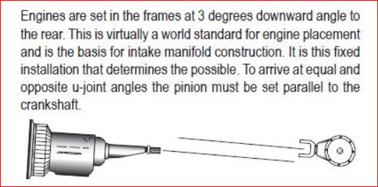
Seems to be a universal standard, they are saying it is determined by the carby placement to be dead level when the vehicle is sitting on a level floor with the weight of the engine/transmission already added. Would imagine diesels would be much the same.
Most critical point made was that the faces of the diff flange and the centreline of the engine/trans output flange MUST be parallel.
OK, back to the numbers read, if my unsprung bare chassis has a reading of 8.2* at the DIFF input flange face, and my engine input/output faces give a reading of 5.7*, it looks like the simplest way is to either shim the diff perches, (feasible, but there should be an easier way to get the two faces parallel by altering the angle of the engine/transmission FIRST).
Again, re-reading the Spicer PDF, a MAXIMUM of 3* is acceptable in inclination, which can be achieved by either using in my case, one short jackshaft, say 1* and the main tailshaft of 2*.
Means I may have to rework my crossmembers, by either adding shims between mounting pads and crossmember supports, OR between the chassis and the crossmembers themselves. Easier to do it now before everything made too permanent.
If I have this right, unless the vehicle is grossly overloaded (which is unlikely) the face angle of the diff input should NOT alter all that much, no more than any other vehicle be it a car or truck, laden or unladen. After all, when vehicles are manufactured, they would have to allow for that vehicles angles to alter slightly and build in a tolerance accordingly.
So, it would seem, again if I have this right (and always willing to be corrected) as long as I set the engine so the driveline input/output faces are parallel, I should be able to set the engine angle inclination at 3* to the chassis rail.
Most important thing would be to take ALL measurement angles with the weight of the major components (engine/transmission(s) in the vehicle) in other words not on blocks on the floor, but on the chassis itself.
I'm probably over-complicating this point, but the last thing I would want is to have to rework all the instillation positions later, better do it now where it's still easily accessible and you can actually see what you are doing.
Dave
Last edit: 6 years 5 months ago by Dave_64. Reason: added text
Please Log in to join the conversation.
6 years 5 months ago - 6 years 5 months ago #188823
by jon_d
"Most critical point made was that the faces of the diff flange and the centreline of the engine/trans output flange MUST be parallel.
OK, back to the numbers read, if my unsprung bare chassis has a reading of 8.2* at the DIFF input flange face, and my engine input/output faces give a reading of 5.7*, it looks like the simplest way is to either shim the diff perches, (feasible, but there should be an easier way to get the two faces parallel by altering the angle of the engine/transmission FIRST)."
Yes.
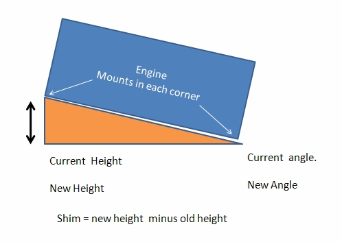
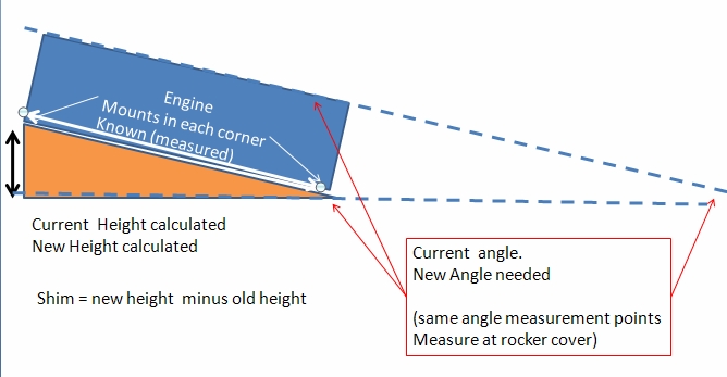
Might be easier to shim the front or rear engine mount.
If you look up the right angle triangle calculators on google and apply it to the engine mounts.
You should be able to shim the front or rear mounts
Replied by jon_d on topic Setting angles of engine/drivelines in chassis
"Most critical point made was that the faces of the diff flange and the centreline of the engine/trans output flange MUST be parallel.
OK, back to the numbers read, if my unsprung bare chassis has a reading of 8.2* at the DIFF input flange face, and my engine input/output faces give a reading of 5.7*, it looks like the simplest way is to either shim the diff perches, (feasible, but there should be an easier way to get the two faces parallel by altering the angle of the engine/transmission FIRST)."
Yes.
Might be easier to shim the front or rear engine mount.
If you look up the right angle triangle calculators on google and apply it to the engine mounts.
You should be able to shim the front or rear mounts
Last edit: 6 years 5 months ago by Gryphon. Reason: fixed up image display
The following user(s) said Thank You: Dave_64
Please Log in to join the conversation.
6 years 5 months ago #188825
by Swishy
OF ALL THE THINGS EYE MISS ................. EYE MISS MY MIND THE MOST
There's more WORTH in KENWORTH
Replied by Swishy on topic Setting angles of engine/drivelines in chassis
Cogz m80
Dun 4 get wen make n the transmission m diff shaft parallel
it needs to B parallel on both planes .......... Horizontal n Vertical
easy to add tapered wedges under spring pack to tilt input shaft plus or minus L8R
Ifn U get my drift
cya
§
Dun 4 get wen make n the transmission m diff shaft parallel
it needs to B parallel on both planes .......... Horizontal n Vertical
easy to add tapered wedges under spring pack to tilt input shaft plus or minus L8R
Ifn U get my drift
cya
§
OF ALL THE THINGS EYE MISS ................. EYE MISS MY MIND THE MOST
There's more WORTH in KENWORTH
The following user(s) said Thank You: Dave_64
Please Log in to join the conversation.
Time to create page: 0.552 seconds