Detroit GM - Overlander's Data Collection
2 years 2 months ago - 2 years 2 months ago #232379
by Lang
Replied by Lang on topic Detroit GM - Overlander's Data Collection
Just been trawling through engineering papers. From what I can see the simple oil pumps in question have limitations. As we know the oil system has two components flow and pressure. The pumps have the capacity to create a flow rate over a wide range in an open pipe and within reason this will increase with speed.
An engine also requires pressure to allow the oil to reach tight places such as bearings and not just find its way out of the easiest holes. They try to control this by changing gallery sizes to account for the local resistance but that is something that can only be averaged eg the big end bearing require more pressure and flow as speed increases because the oil is being "squeezed" out by increasing force but the main bearings can run pretty well on the average allowed by their oil gallery ports.
Although it is not exactly the electricity equivalent the work of the oil is is similar ie Volts(pressure) X Amps (flow) = Watts (the "work") to retain the same work if one goes down the other must go up. In electricity we keep the volts constant and change the Amps to vary our work capacity.
In the oil pump we want the pressure to remain sufficient to oil the bearings at the highest possible speed this is regulated by a spring valve so it is not too high at low speed and not too low at high speed. We can see this plainly by revving the engine and looking at the oil gauge as it falls between a fixed lowest and highest position on the spring valve.
All liquid pumps have a maximum possible flow dictated to by their internal design and the size of the pump and pipes. The one in a vehicle engine has enough for all normal purposes and if left fully open at the outlet would continue to pump more and more according to speed until it reached the limitations of its design, size, piping, fluid viscosity etc.
This is what we see in those graphs. The pump can only do so much work by design so as the engine speed increases the oil is having to push open the regulator valve more and more and the energy required to do that starts to impinge on the design capacity of the pump. In a badly worn engine the oil is pouring through the wider gaps which no longer assist the regulator valve with natural built-in back pressure. Like having a split in a garden hose.
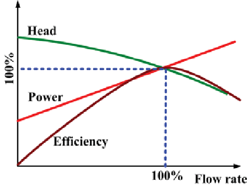
This chart is what happens to all pumps of any fluids. In a vehicle the oil pressure regulator valve can be said to be "head" on say a water pump ( a real water pump not a circulating water pump as in a car engine).
When it reaches its optimum design capacity everything - head (pressure) and flow is all downhill from there.
To answer Paul's question. If we imagine the red power line to be revs which it roughly is for the pump (the pump draws so little power it does not know the total engine output is following a curve and is always supplied with its full needs at increasing rpm) where the graph runs out can be said to be the engine rev limit. Although the flow and pressure are falling badly the engine has been designed that they are sufficient until it throws a rod from mechanical forces not lack of lubrication.
An engine also requires pressure to allow the oil to reach tight places such as bearings and not just find its way out of the easiest holes. They try to control this by changing gallery sizes to account for the local resistance but that is something that can only be averaged eg the big end bearing require more pressure and flow as speed increases because the oil is being "squeezed" out by increasing force but the main bearings can run pretty well on the average allowed by their oil gallery ports.
Although it is not exactly the electricity equivalent the work of the oil is is similar ie Volts(pressure) X Amps (flow) = Watts (the "work") to retain the same work if one goes down the other must go up. In electricity we keep the volts constant and change the Amps to vary our work capacity.
In the oil pump we want the pressure to remain sufficient to oil the bearings at the highest possible speed this is regulated by a spring valve so it is not too high at low speed and not too low at high speed. We can see this plainly by revving the engine and looking at the oil gauge as it falls between a fixed lowest and highest position on the spring valve.
All liquid pumps have a maximum possible flow dictated to by their internal design and the size of the pump and pipes. The one in a vehicle engine has enough for all normal purposes and if left fully open at the outlet would continue to pump more and more according to speed until it reached the limitations of its design, size, piping, fluid viscosity etc.
This is what we see in those graphs. The pump can only do so much work by design so as the engine speed increases the oil is having to push open the regulator valve more and more and the energy required to do that starts to impinge on the design capacity of the pump. In a badly worn engine the oil is pouring through the wider gaps which no longer assist the regulator valve with natural built-in back pressure. Like having a split in a garden hose.
This chart is what happens to all pumps of any fluids. In a vehicle the oil pressure regulator valve can be said to be "head" on say a water pump ( a real water pump not a circulating water pump as in a car engine).
When it reaches its optimum design capacity everything - head (pressure) and flow is all downhill from there.
To answer Paul's question. If we imagine the red power line to be revs which it roughly is for the pump (the pump draws so little power it does not know the total engine output is following a curve and is always supplied with its full needs at increasing rpm) where the graph runs out can be said to be the engine rev limit. Although the flow and pressure are falling badly the engine has been designed that they are sufficient until it throws a rod from mechanical forces not lack of lubrication.
Last edit: 2 years 2 months ago by Lang.
Please Log in to join the conversation.
Less
More
- Posts: 538
- Thank you received: 2455
2 years 2 months ago #232386
by overlander
Replied by overlander on topic Detroit GM - Overlander's Data Collection
Lang all Detroit engines have a regulator valve and a relief valve. Paul I have no explanation for your question. Pete
Please Log in to join the conversation.
2 years 2 months ago #232389
by Lang
Replied by Lang on topic Detroit GM - Overlander's Data Collection
Pete
That is right I believe. I think they operate to keep the oil pressure within the range but the pump efficiency deteriorates as in the GM graph Paul mentioned with rpm affecting flow.
That is right I believe. I think they operate to keep the oil pressure within the range but the pump efficiency deteriorates as in the GM graph Paul mentioned with rpm affecting flow.
The following user(s) said Thank You: PaulFH
Please Log in to join the conversation.
Less
More
- Posts: 538
- Thank you received: 2455
2 years 2 months ago #232391
by overlander
Replied by overlander on topic Detroit GM - Overlander's Data Collection
You know we were never told any of that stuff during weeks and weeks of Detroit training courses- the branch has to have 'X' amount of product trained mechanics to keep their accreditation with Daimler. Bit like TAFE- everyone passes. Of all the 2 Strokes I built so long as they passed muster on the engine dyno and hadn't developed any oil leaks before going to get painted then all was good. And even better for when the next time you saw the engine it was only back for a scheduled build on hours worked or in the case of a certain government department having untrained mechanics[?] mess with the engine. Pete
The following user(s) said Thank You: Mrsmackpaul, PaulFH
Please Log in to join the conversation.
2 years 2 months ago #232392
by JOHN.K.
Replied by JOHN.K. on topic Detroit GM - Overlander's Data Collection
I once bought a big stack of 4-71s and 6-71s from QGR for scrap...every one had a rod thru the block.....so theyd be good for pistons and liners ,and maybe a head............they never had blowers on them ,and a guy at QGR reckoned the apprentices would blow up motors just so they could steal the blower.................anyhoo,be that as it may,some of the motors were just about new.
The following user(s) said Thank You: overlander, PaulFH
Please Log in to join the conversation.
2 years 2 months ago - 2 years 2 months ago #232393
by Lang
Replied by Lang on topic Detroit GM - Overlander's Data Collection
I had a bit more of a look at engineer pump theory.
Paul suggested the pumps fall off because they might cavitate.
This is "sort of" correct. The valves, vanes, pistons, fins, screws or whatever the style can only be perfect at one speed. Some designs are better than others at coping with a speed range. Once they are outside that optimum speed they become inefficient and that is why they fall off at both the top and bottom end.
The most obvious demonstration of this we see is boat and aircraft propellers.. For instance a ski boat will have a very fine pitch prop which gives great thrust at low speed but it soon dies as the boat accelerates and will over rev quite quickly like being in first gear in a car. On the other hand a race boat will have slow acceleration and the prop will be pitched to the optimum thrust at maximum speed/horsepower/torque.
Aircraft are the same. Say a Piper Super Cub with a fine pitch short field fixed pitch prop will max out on the tacho red line at 85 knots but get off the ground and climb like a rocket. The same aircraft with a cruise pitch prop will take as much as twice as long to get off the ground (like starting a car in top gear) but may cruise at 105 knots.
Commercial boats and larger aircraft have solved the problem with variable pitch props to allow optimum effort right through the speed range.
We can not do that with the "prop" on an oil pump so are in the Piper Cub situation of choosing a setting for perfection at particular rev point and accept the inefficiency up or down from that speed. The main thing is to fit a pump that still provides sufficient oil at the worst speed but aim for maximum efficiency at the normal cruising speed.
Last edit: 2 years 2 months ago by Lang.
Please Log in to join the conversation.
2 years 2 months ago - 2 years 2 months ago #232394
by JOHN.K.
Replied by JOHN.K. on topic Detroit GM - Overlander's Data Collection
GM went to great lengths to limit oil consumption with the 92s.........oil flow to the piston crown is via a drilled hole in the rod....and in the crosshead piston engines ,wrist pin which has a small central hole between the boltholes...........the big deal is to stop oil from being blown in thru the liner ports and burnt.......GM invented all kinds of special rings and bore finishes ..........and as we know finally gave up..,and went to 4 strokes.
Last edit: 2 years 2 months ago by JOHN.K..
Please Log in to join the conversation.
2 years 2 months ago - 2 years 2 months ago #232395
by JOHN.K.
Replied by JOHN.K. on topic Detroit GM - Overlander's Data Collection
Actually,I admit I dont know.......the crosshead piston has a sort of half bearing that goes all across the top.....it just sort of clips in place,before you bolt the rod onto the pin...........Ive got some crosshead pistons laying about ,I must have alook at one.............Its actually quite anazing ,when I quit work ,GMs were just scrap....no one wanted one for anything..........I also didnt mentio the piston is two loose pieces ,which are held together by the pin.
Last edit: 2 years 2 months ago by JOHN.K..
Please Log in to join the conversation.
2 years 1 month ago #232633
by PaulFH
Replied by PaulFH on topic Detroit GM - Overlander's Data Collection
The following user(s) said Thank You: oliver1950
Please Log in to join the conversation.
Time to create page: 0.649 seconds